Voltage Controlled Switch Manual Usage and installation manual
This is the usage and installation manual of the Voltage Controlled Switch.
Automatic mode
This describes the behaviour in automatic mode. At any time, the output can also be switched manually.
The Voltage Controlled Switch works on 12V and 24V systems, in the latter case it detects the 24V system and uses the 24V setpoints. These are indicated below between parenthesis.
Switchover voltage
- The output switches to ON when the voltage raises to 14V (28V). This voltage indicates a nearly full battery and the presence of a charge current.
- The output switches to OFF when the voltage drops below 13.5V (27V). This voltage indicates the absence of a charge current.
These voltages work well with lead acid batteries as well as with lithium batteries, however you can configure the ON and OFF voltages indiviually, and even reverse the operaton (switch the output OFF above a certain voltage).
Hysteresis
The difference between the ON and OFF voltage is called the hysteresis. The hysteresis serves two purposes:
- It prevents alternating between the ON and OFF state when switching ON causes a slight voltage drop.
- It waits until the battery is reasonably charged but keeps the output ON when the charger goes into float mode.
The hysteresis can be configured differently by configuring a specific OFF voltage.
Time restrictions
- Once OFF, the output will not switch to ON unless at least one minute has passed, regardless of the voltage.
- Once ON, the output will not switch to OFF unless at least 5 seconds have passed, regardless of the voltage.
These timings are not configurable.
Usage
The Voltage Controlled Switch is equipped with a touch sensor and an indication LED.
Three operation modes
The Voltage Controlled Switch has three modes:
- Automatic, where the output is switched according to the voltage
- Manual off, where the output is switched off regardless of the voltage
- Manual on, where the output is switched on regardless of the voltage
After a mode has been in use for two hours, it will be saved, so that after a power loss the same mode is choosen again.
Switching between the three modes
Control of these modes is very intuitive:
- A short touch switches the output into the opposite state, i.e. if it was on, then it becomes off, and if it was off, it then becomes on. Logically, this is a persistent override (manual mode).
- A long touch sets the operation mode to "voltage controlled". This mode is cancelled again when a short touch is used to switch the output into a manual mode.
LED indication
- In manual OFF mode, the LED is steady OFF.
- In manual ON mode, the LED is steady ON.
- In automatic mode, if the output is OFF, the LED is OFF with a periodic short flash.
- In automatic mode, if the output is ON, the LED is ON with a periodic short interruption.
Setting the switchover voltages
The default ON and OFF voltages are well choosen, but you can configure them to suit your specific needs.
Configuring the ON voltage
Switch to automatic mode when the desired ON voltage is present, and hold the button for at least 8 seconds. The LED starts blinking, and after the 8 seconds have lapsed it starts blinking rapidly to indicate that you can release the button. When the button is released, the current voltage is stored as the ON voltage. The off voltage will be automatically configured to be 0.5V (1V) lower.
Configuring the OFF voltage
In most cases it is not necessary to configure the OFF voltage, as it will be automatically 0.5V (1V) lower than the configured ON voltage. There can be two reasons why you would want to configure an OFF voltage:
- When you want a different hysteresis than the standard 0.5V (1V).
- When you want to use the Voltage Controlled Switch in reverse mode, i.e. that it switches OFF above a certain voltage, and ON below a certain voltage. In this case, you configure the OFF voltage to be higher than the ON voltage.
Note that you must set the OFF voltage after you have set the ON voltage, because setting the ON voltage automatically overwrites the OFF voltage with the ON voltage minus hysteresis.
Switch to automatic mode when the desired OFF voltage is present, and hold the button for at least 12 seconds. The LED starts blinking, after 8 seconds it starts blinking rapidly, and after 12 seconds it blinks slowly again, indicating that you can now release the button. When the button is released, the current voltage is stored as the OFF voltage.
Hardware installation
There are three installation options.
Panel mount
Panel mount means that you install the Voltage Controlled Switch into a panel. This can be an electrical control panel, but also a wall which has an open space behind it. The frontpanel will be flush with this panel and all wiring will be behind the panel, resulting in a very neat and practical installation.
You need to make a cut out of 40x30mm. Since the front panel of the Voltage Controlled Switch is larger, there is some room for error.
The frontpanel will be screwed to the panel with the two supplied 3mm stainless steel Allan bolts. If you drill a hole of 2.5mm, and wiggle the drill a bit, you can usually screw in the Allan bolts without tapping. This works in plastic, wood, fiberglass and aluminium. Alternatively you can use a 3mm drill and use nuts to secure the bolts.
Box mount
An enclosure is used when panel mount is not possible. Secure the enclosure onto a wall and pull the wires inside, connect them, and screw the frontpanel onto the enclosure with the two supplied stainless steel Allan bolts.
Cabinet mount
In this case you mount the circuit board without front panel in an enclosure which can be mounted out of sight. You either don't use any interface at all (which means the switch operates in automatic mode all the time) or you connect an external switch (and indication LED) according to the schematics below.
Electrical installation
Most likely you want to switch a DC load. If you want to switch an AC load (110V-240V) refer to the chapter below.
DC load
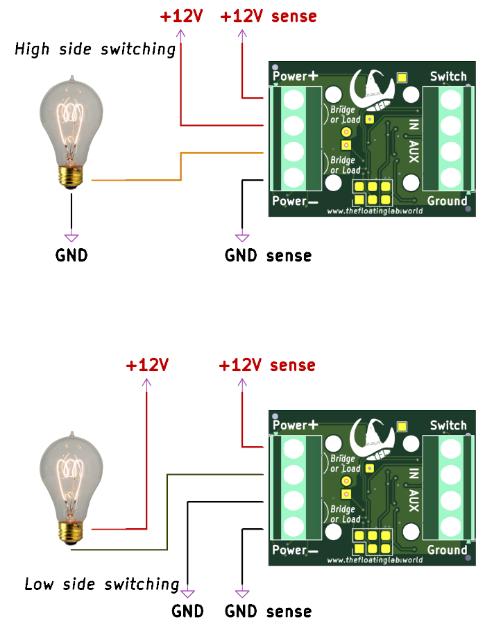
The Voltage Controlled Switch can be used to switch a load on the high side as well as on the low side. See the illustration for the difference.
High Side versus Low Side switching
With high side switching, the load has a fixed connection with the ground (minus) and the Voltage Controlled Switch switches the plus.
With low side switching, the load has a fixed connection to the plus, and the Voltage Controlled Switch switches the minus.
If you are building a new installation, high side switching is the most intuitive. It has the advantage that when the load is switched off, no live voltage is present at the load.
But in an existing situation one of the sides of a load is already connected to either the plus or minus, and in that case you pick the configuration which requires the least amount of wire changes.
Sense wires
It may look possible to interconnect all 12V and GND wires together, and then run just one of each to the system bus. In fact, you can do so if the wires are short and you only switch a light load (about 1 Amp).
However, with longer wires and with higher loads, it is best to run all wires individually to the system bus. You see, with longer wires and a heavy load, there is going to be some voltage drop in the wires, and the Voltage Controlled Switch would interprete this voltage drop as a drop in battery voltage. This would manifest itself by turning the load off 5 seconds after it has been turned on, and then after one minute to switch it on again, etc. If the sense wires are routed separately to the system bus, the Voltage Controlled Switch would see the voltage as present on the system bus, without the voltage drop in the wires to the load.
Fuses
All devices must have a fuse or circuit breaker in the plus wire between them and the battery! The maximum amperes depend on the normal power consumption of the load, it should be some 25% higher than what the load consumes. Fuses are to protect the wires from a melt down, but the wires should of course be sized for the expected amperage.
The Voltage Controlled Switch and the load can be connected via the same fuse or circuit breaker, however if you use a separate sense wire (recommended!) this sense wire needs to have its own fuse. A commonly available glass fuse of 100 to 250mA would be sufficient for this purpose.
AC load
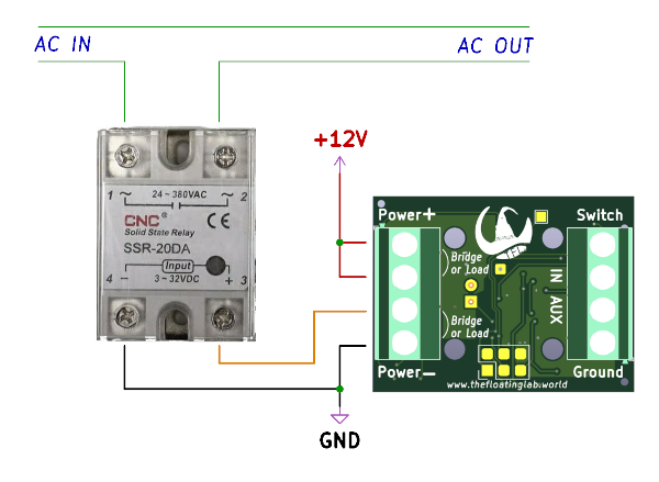
To switch a high voltage AC load (110V-240V) you need a Solid State Relay. The control terminals of the SSR are polarity sensitive, so observe the minus and plus sign.
AC wires usually have the colors brown and blue (and optionally green-yellow for earth), and although it doesn't really matter, by convention you splice the relay in the brown wire and let the blue (and green-yellow if available) pass through.
Note that high voltage AC can be dangerous, if you buy the SSR from us then it comes with an enclosure that makes touching the terminals impossible while facilitating sufficient ventilation.